 info@optoga.com
 +46 589 490 950


Technical advances in using AC
There have been big advances in AC LED technology in recent years driven by its ease of use and omnipresence of 230VAC. As a result a large part of next generation LED research is focussed on 230VAC. The trend is to miniaturise AC solutions and this is when drivers, rectifiers and surge protection become critical. There are solutions where LEDs can be directly AC driven, but this leads to a problem with visible flicker. These diodes have special etched circuits so they can be driven in both directions, which means that half the LEDs are turned on while the others are turned off. The problem is that there is a relatively long time period when all of them are not receiving power at the points when the sinus curve passes 0° and 180° respectively. There is a new technology which is better.
The new technology is even more interesting when we consider miniaturisation in relation to new and expected regulations. The regulations are expected to be based in many aspects on IEEE1789:2015 and as is often the case the USA has taken the lead in this area. It is expected that IEEE1789:2015 will influence new directives from the governing Lighting Europe committee.
At the same time there is new technology for handling AC as described here.
What is flicker
In principle, all light sources that are supplied with 230VAC have some level of flicker (intensity variations in the emitted light) and can be found in fluorescent tubes, low power bulbs and LEDs. This has become a greater problem when moving to LED technology as they do not have any “after glow” unlike practically all other light sources. The problem often increases when the light source is dimmed. It is a problem that should and can be avoided, but due to cost is often removed for budgetary reasons as the consumer is usually not prepared to pay for it.
Flicker is measured in the emitted light from a light source.
Flicker is visible when the intensity fluctuation is below 75-80Hz and is not seen by eye when above around 100Hz, however the brain can detect it up to approximately 500Hz. It affects us negatively when both visible and non-visible and is well documented in research. It can cause headache, migraine, distraction and even epilepsy as well as cause problems when looking at moving objects.

USA standard includes flicker
A new standard, 1789-2015, “Recommended voltage fluctuations in high intensity lamps to reduce risk to user health” released by IEEE june 2015,
Defines acceptable levels of flicker as follows: Max. Percentage flicker = power supply frequency x 0.08%/Hz, the highest Flicker Percentage at 100Hz (50Hz supply) and 120Hz (60Hz supply) to be 8% and 10%
This means 8% flicker in Europe and 10% flicker in the USA.
US Departement of Energy
The US Department of Energy has come up with recommendations which are beyond what the industry has been expecting. We are waiting to see how this develops in Europe.
LAPLACE investigations in France
Research in France has shown that 20% flicker percentage is acceptable which is precisely what CFLs have. Incandescent bulbs have 10%. In addition they have carried out further research on this which states that IEEE 789 is a recommendation and should not be taken as a standard.
A 100W light bulb has a flicker percentage of 10%
A CFL has a maximum flicker percentage of 20%
European Standard
In Europe we are waiting to see what standard becomes established and CIE are still working on this. In the meantime the German lighting organisations will make their own directives. They will probably become the leading standards for the rest of Europe.
Flicker comparison
There are three design options.
- Resistor
- Sinus wave control of LED strings
- Sinus wave control with smoothing
Flicker test AC (resistor solution)
First consider a string of LEDs connected in series. On the input side we assemble the diodes to reach 230V which has been rectified and regulated using resistors. The first thing we notice with this very simple design are very poor flicker values. This is because the LEDs require a relatively high forward voltage to turn on.
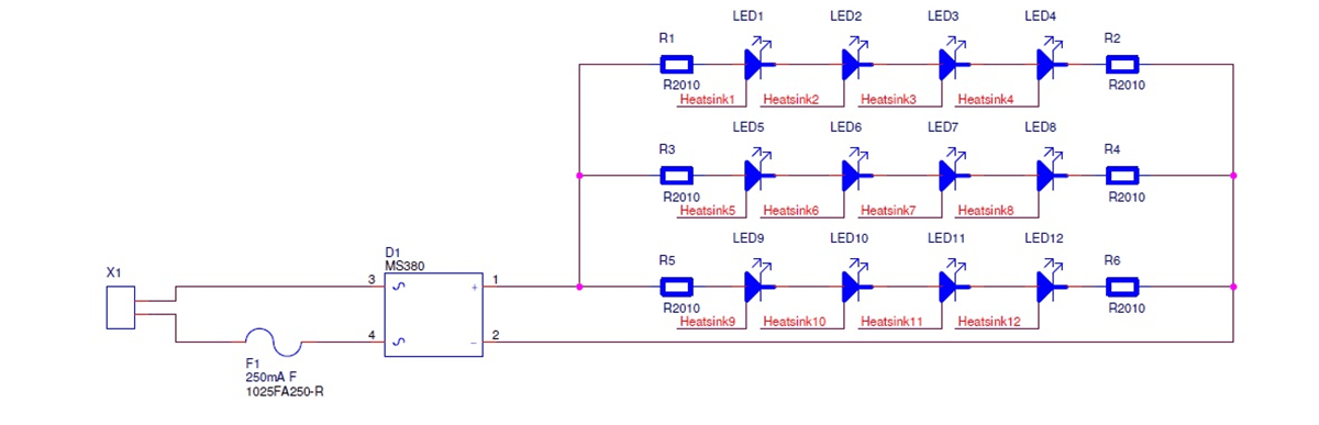
- A relatively simple design mounting LEDs after a rectifier which has a total Vf of 230V.
 When we measure the light output at 100Hz we notice that they have a relatively long “off” period between being turned on.
In summary, we can see a flicker percentage of 100%, a very poor Flicker Index as well as a very poor flicker modulation. We can often detect the flicker with the naked eye. We can see very long time intervals where the LEDs are not on (off time).
Max = 2.03V
Min = 0
Average = 0.863V Frequency = 99.89Hz
F% = 100%*(2.03-0)/(2.03+0) = 100% FI = 0.311
FM = (2.03-0)/0.863 = 2.34
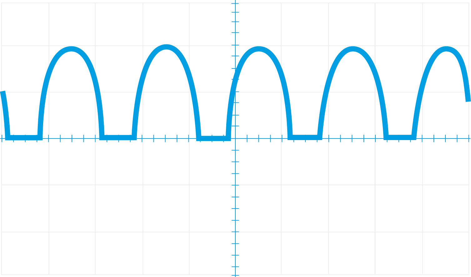
Flicker test AC with IC
A design improvement using an integrated circuit where we turn on all the the diodes in 4 stages. This means that we can use a lower forward voltage Vf for the LEDs which does not need to be the full 230V (max peak 335V) but is only a quarter of 230V at about 60-62V.

- Above we see how the IC circuit turn on the LEDs in stages

- Above we see the 4 LED strings that are turned on and off with the sinus wave.

- Above we can see how the light looks at 100Hz and we can see the on/off stages
We now have a completely different performance. We have the same low Ficker Percentage (100%) but we have a much improved Modulation Index and an improved Flicker Index. The staircase steps when the various LED groups turn on and off can be seen. In addition we have a much improved Power Factor (Pf) of 0.97 as opposed to 0.60.
Max = 2.03V
Min = 0
Average = 1.175V Frequency= 100.17Hz
F% = 100%*(2.03-0)/(2.03+0) = 100% FI = 0.2196
FM = (2.03-0)/1.175=1.73
Flicker test using AC with IC and Electrolytic Capacitors
If we go one stage further in the design we can smooth out the LED strings using capacitors while still using the IC. The advantage with this is that using relatively simple means we can reach an acceptable level while keeping the Pf of 0.97. If we need to achieve a flicker under 8% there is a quite a large number of capacitors which means that a switching solution becomes attractive. We will most likely need to have solutions using additional capacitor banks depending on efficiency and Pf control.

- Above is a standard solution with 4 E-Caps that smooth out the Flicker Percentage They are contacted after the rectifier and together with the LEDs maintain the Pf.


- Above we see the light pattern at 100Hz frequency and we can see that the various stages of on/off cannot be seen as they have been smoothed out.
We can see with this design that we have a smoother distribution with a Flicker Percentage of 36.3% and a much improved Modulation Index as well as a very good Flicker Index. This without trying to get below a predetermined level. In further experiments we have been able to get down to 7% Flicker Percentage by playing with the capacitor values.
Max = 2.08V Min = 0.972V
Average = 1.535V Frequency = 100.21Hz
F% = 100%*(2.08-0.972)/(2.08+0.972) = 36.3%
FI = 0.0787
FM = (2.08-0.972)/1.535=0.72
As can be seen there is a great deal of energy that needs to be stored within the curves which means large capacitor banks.

 info@optoga.com
 +46 589 490 950